Chosen design
This is from “Summary Report on Investigation of Miniature Valveless Pulsejets”, 1964.
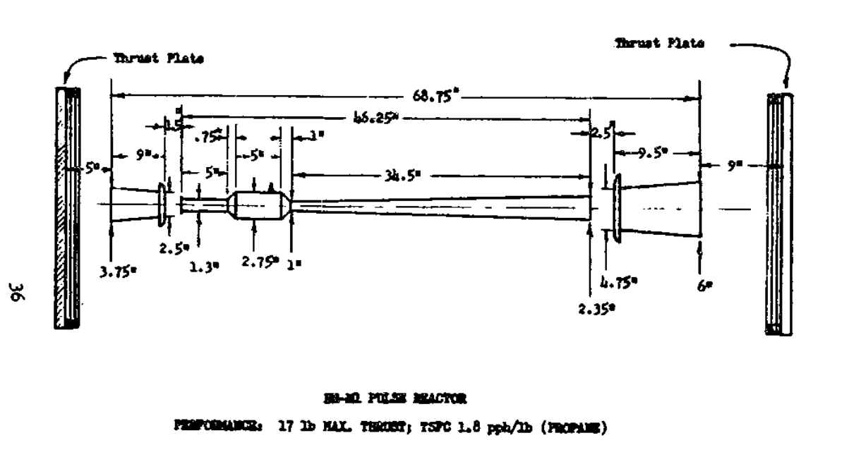
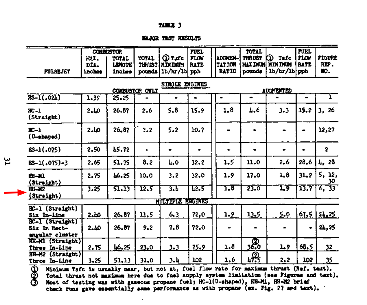
Picked this one (I think it was this one?) because it was straight, valveless, and had actual performance data associated with it.
CAD
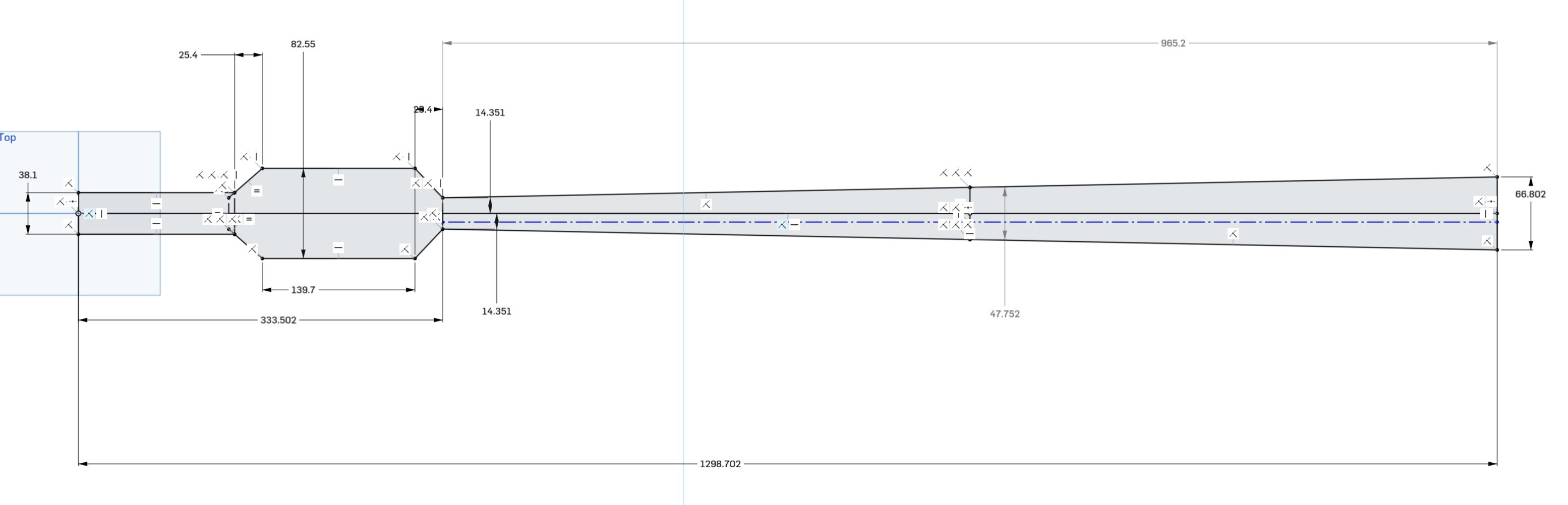
This got ordered from sendcutsend - the inlet and two tail sections were just ordered as three copies of the outer tail section to save on bom cost, and also that gets a bunch of scrap material for later:

Combustion chamber welded up
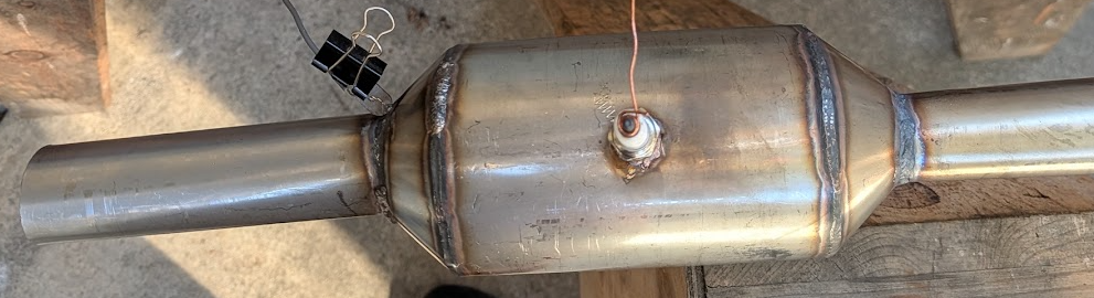
This was done with a couple kw laser welder. Makes things pretty easy.
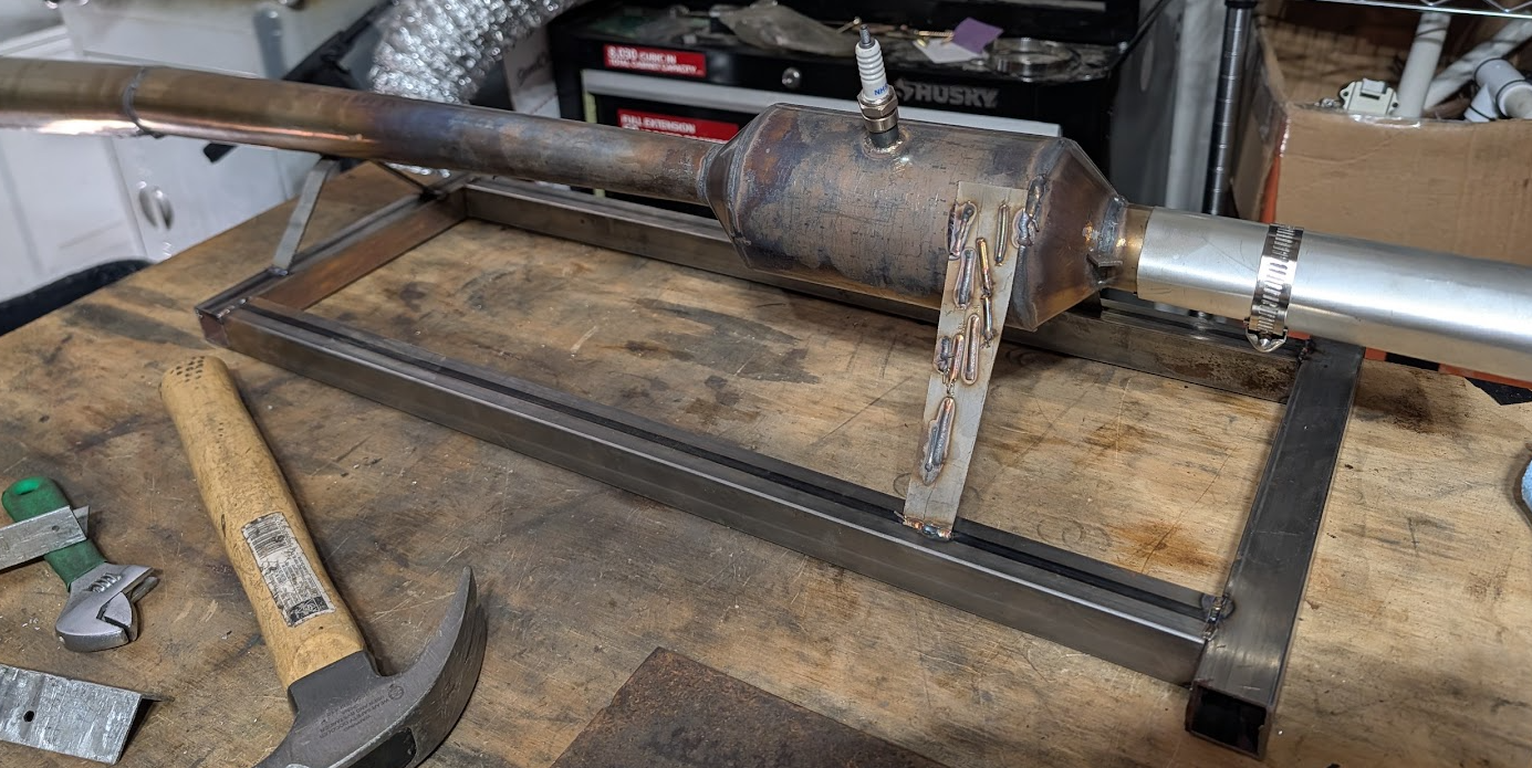
On a stand
Extra high emissivity paint
One idea for observing where the combustion is happening is to just look at the device with a thermal camera. As it is, however, the shiny metal surface is no good as it’s too reflective. But a quick coat of a magnetite/bentonite slurry gives good results:
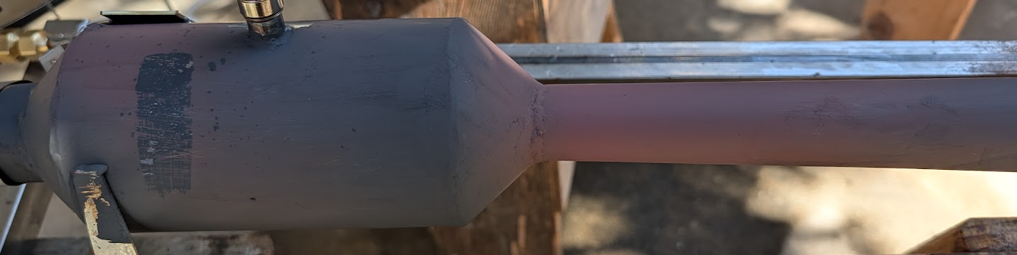
In the above picture you can see that the area just after the combustion chamber somehow got partially converted from Fe3O4 to Fe2O3. Although it’s clearly because it reached a higher temperature, interestingly it seemed to only occur after the heating during the cooling stage when the vessel wall was only a couple hundred C.
Stability, or lack thereof
This is where we ran into troubles. The pulse jet can be started if the fuel injection tube is positioned in the right location. The right location seems to be just inside the combustion chamber, with the fuel injection tube pressing up against the wall of the chamber, not in the center. Why? I don’t know.
Slow motion (1/8x) speed flame combustion
Doesn’t really look like there’s much to learn here.
On starting with and without a compressed air nozzle
We were starting the pulse jet using a compressed air gun as a source of air as opposed to a leaf blower or ducted fan. Interestingly the pulse jet starts up well when the restriction is used on the end, but not when it isn’t:
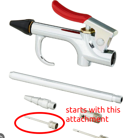
This could be either because the narrow jet of air is more turbulent and does a better job of fuel-air mixing, or (more likely) just that the fast jet entrains more air in a venturi effect and so more is delivered down the inlet of the pulse jet.
Pressure sensor idea
The academic literature generally uses piezo transducers to measure the pressure waves at a number of points across the combustion chamber of a pulse jet. There is a problem with this though:
- A piezo element is inherently sensitive to vibrations, since as you accelerate it back and forth a force is placed across it
- The wall of a pulse jet is subject to huge vibrations Hence, the piezo element will pick up a large signal that is of the same frequency of what you are trying to measure. If you aren’t careful in isolating and calibrating out the signal you want the results will look quite plausible and be completely wrong. Most pulse jet papers that have a waveform in them of the pressure at various points in the combustion chamber, for example the german one that is so promising for supersonic operation. But unless they account for this the results will be garbage most likely.
So how about this idea:
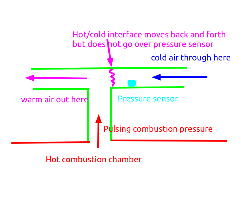
I feel like this could actually work. Mr claude of course agrees, but I did not find its analysis convincing.
However it does have the problem that you have to make a new one for each new location that you want to measure the pressure at.
Pressure sensor idea 2
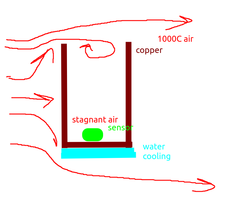
A better idea that was suggested to me would be to have a pressure sensor on the end of a stick, and then sweep the stick down through the pulse jet. The pressure sensor would of course have to be water cooled somehow, but the idea here is that if you put the pressure sensor down the end of a tube with a long enough l/d ratio, then maybe the airflow at the bottom would become stagnant, and so the head transfer into a small sensor at the bottom would not be that bad. Something like this:
Pressure sensor idea #3
I buy a noncooled pressure sensor like this one, a XCQ-093-50SG and stick it in a cooling jacket. Like this:
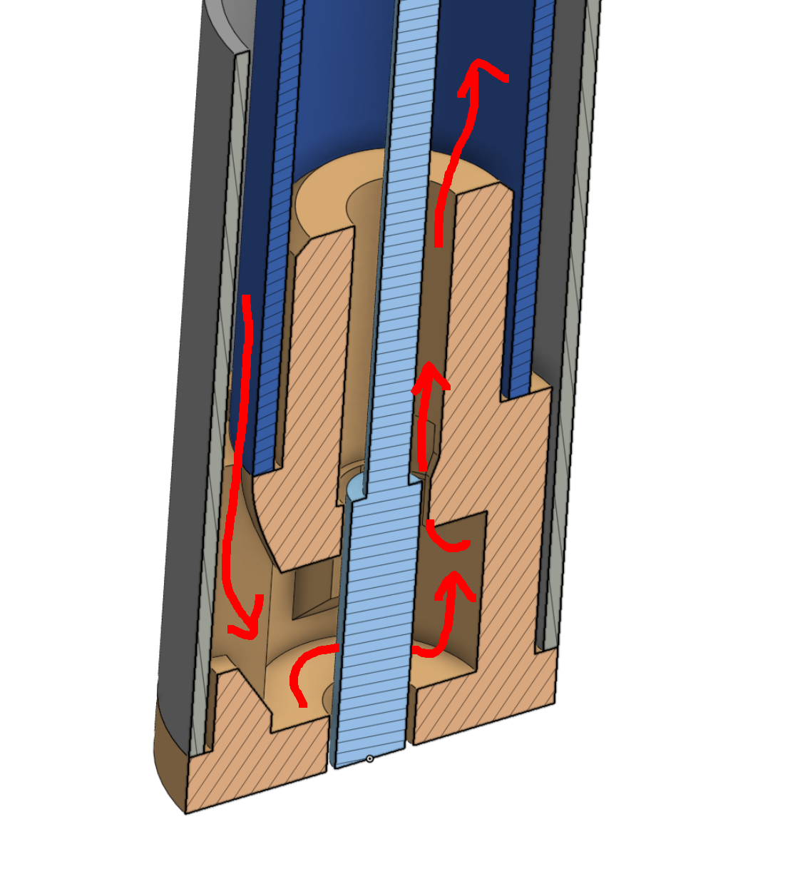
The orange part above can be printed from stainless steel for cheap, and goes inside two stainless steel pipes. The wire for the sensor will go all the way up the center pipe. At the other end of the pipes I’ll 3D print some doodad to enable water in/out + electrical connections. Then, since the whole thing is a 1/2” rod basically, hopefully it can be swept down the combustion chamber whilst the combustion chamber is running and the direct pressure vs axial distance function can be obtained (with the aid of one external microphone to get a phase reference.)
Provided that the pressure sensor does not interfere with the operation of the pulsejet this will be far superior to the “3-4 monitors going through the case” tactic that most people seem to use.
Simulation
I gave the above section alongside the relevant step files to Mr Sol medium and told it to calculate the flow resistance. It came up with this interactive 3D CFD report.
You can see from it that there is a constriction at the three vents that lead to the outer annulus for the return path (point 2) and also at the construction where it has to go around the actual sensor (point 1):

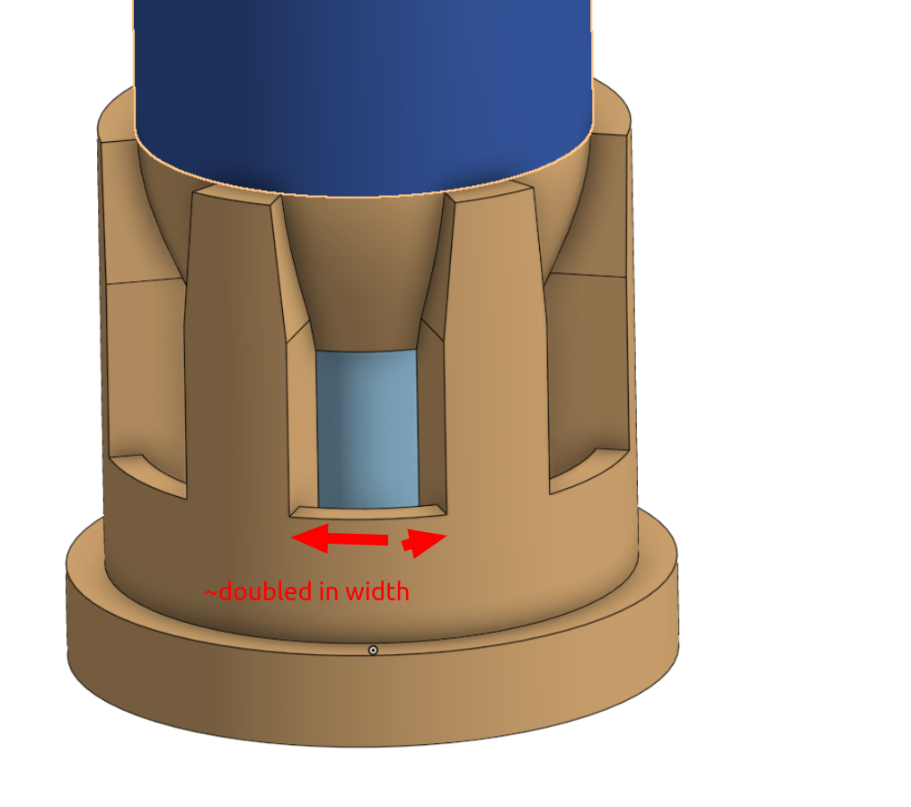
These results actually look pretty good - this is the first time I’ve gotten useful one-shot CFD results out of a model. You can see that a lot of the pressure is being dropped around the three slots that connect to the outer annulus of fluid, so I increased their size by a lot and put a small taper at the top:
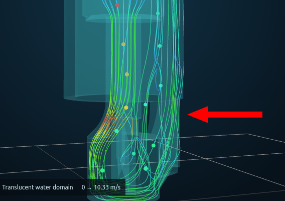
Re-running the simulation gives these updated 3D CFD results. You can see now that the previous restriction is gone:
Clearance vs press fit
I had originally intended the tubes to be epoxied in place, but perhaps that won’t work out for thermal reasons. So I added a variance that does a press fit on the end:
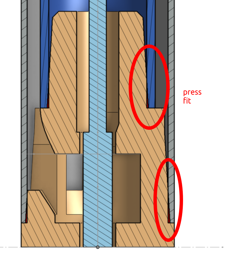
Hopefully we can rescue the design if the gluing doesn’t work out.