The time has come to build an interferometer.
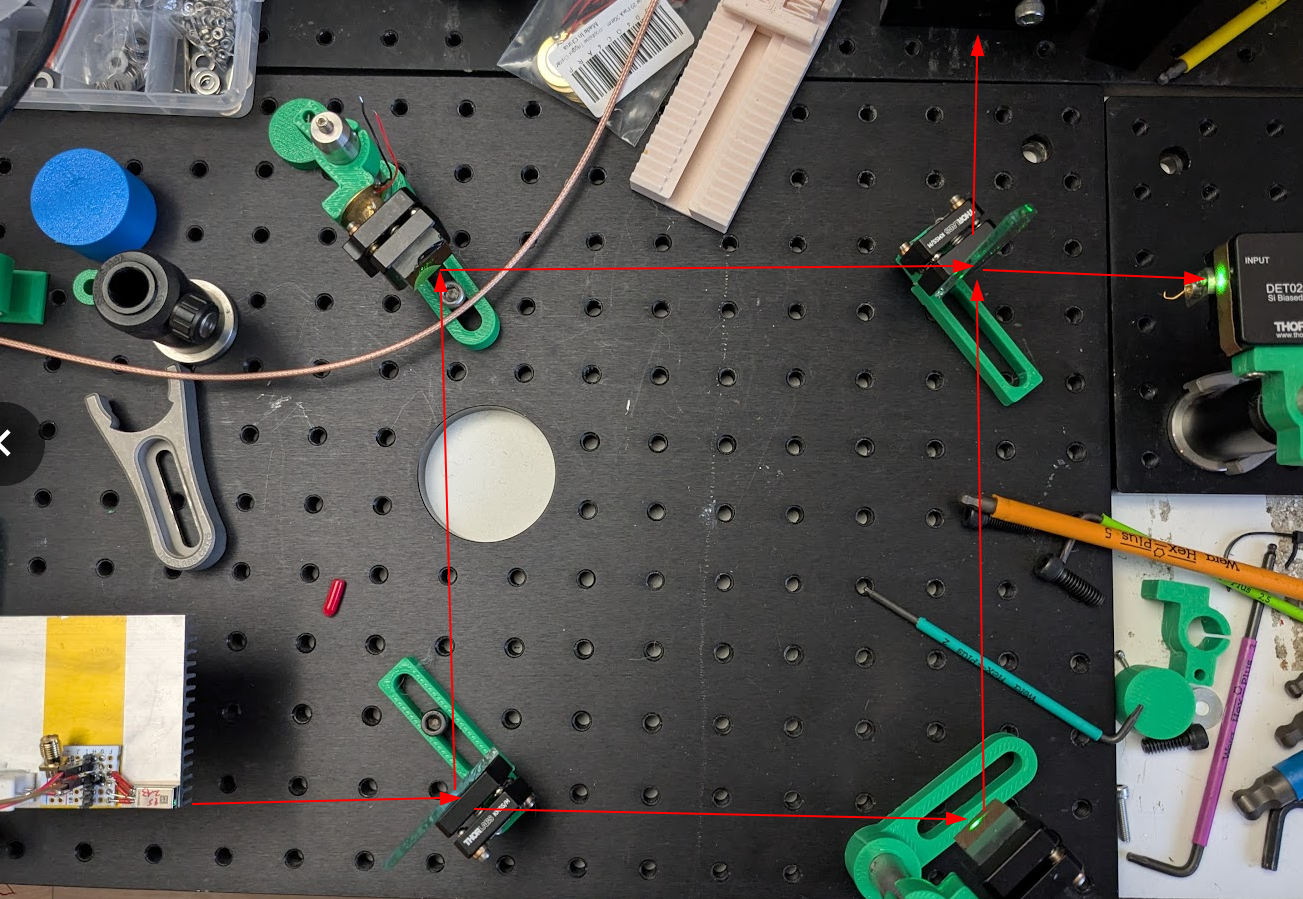
Here is the setup:
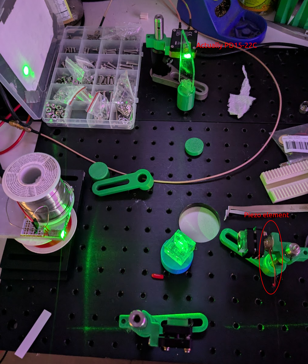
The laser is a osram PL530 being operated at 270ma with no power to the heater. This is apparently 50mW @ 450mA but honestly it didn’t look that bright when I was operating it at 270mA.
Here is the output of the photodiode I installed inside an old thorlabs case:
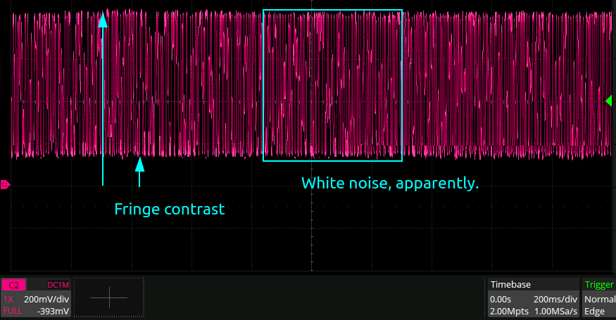
This is with the scope on 1MOhm input impedance. Pretty good fringe contrast, really! I also installed a piezo disc on one of the mirrors on the right hand side with the idea that since there was so marge garbage in the output signal from vibrations through the table and a generally bad laser, a clear 1khz tone from the piezo would stick out really well and prove the interferometer was working well. Uncle GPT however informs me that since the thickness of the piezo film is likely only about 100um, the displacement would be on the order of single digit nm. So not enough to show up anyway.
Three level signal
The next day I turned the interferometer on and noticed there was a kind of four-level distribution:
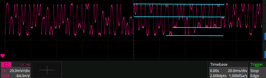
Looks like I have two interferometers in my interferometer.
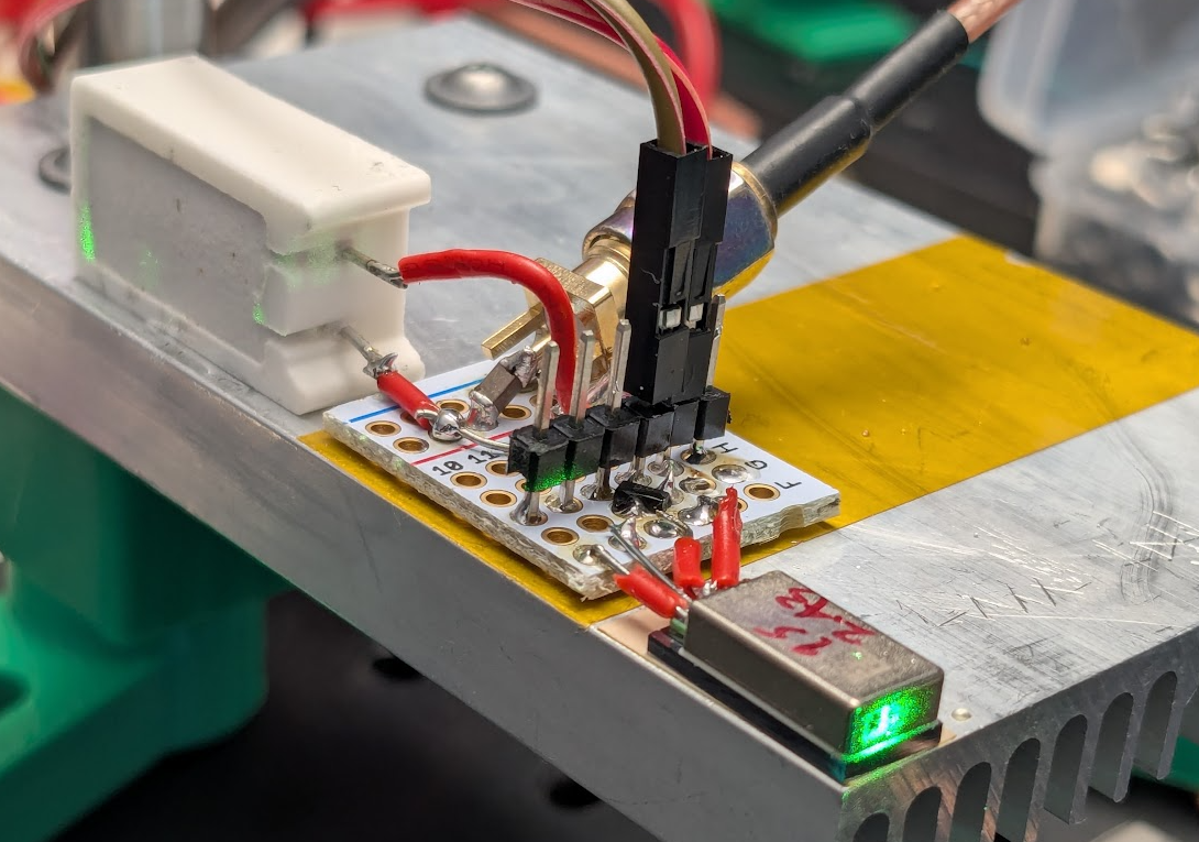
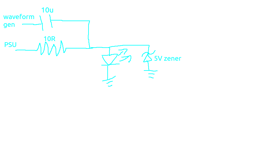
Current modulation.
Now I am powering the laser through a 10R resistor, and am AC coupled to a waveform generator so I can inject some current modulations.
Sitting still
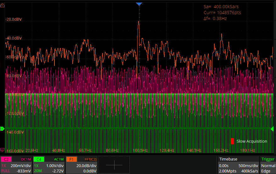
With a 4VPP modulation coming out of the scope waveform gen, I get this.
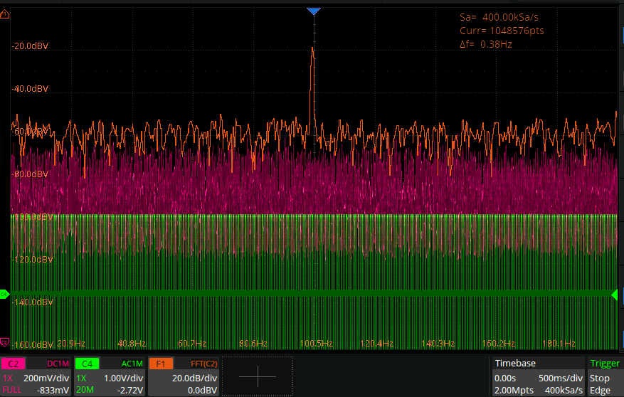
Whilst tapping.
Continuously lightly tapping on the table shifts the noise up in frequency quite a lot and makes the modulation a lot more obvious:
One arm blocked
With one arm of the interferometer blocked, I get this:
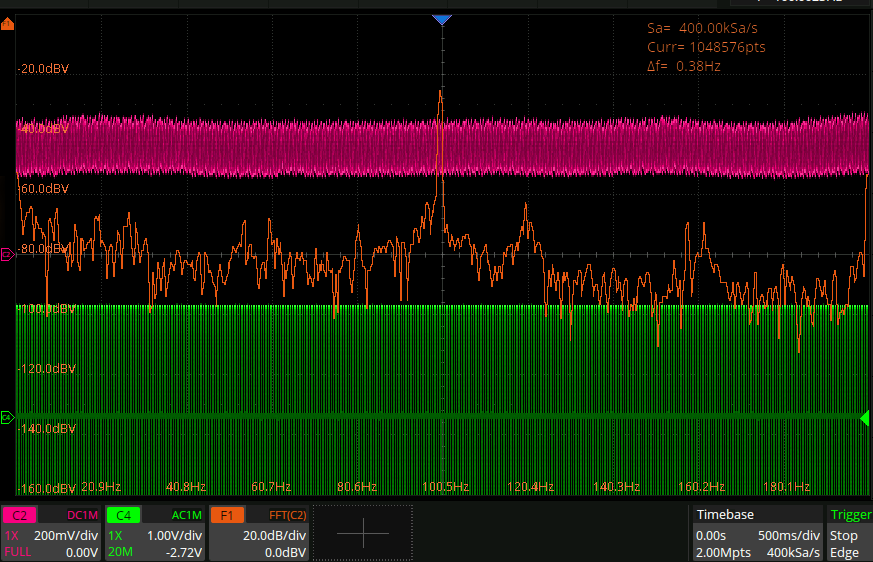
…I guess the signal is just modulation of the laser power…
Michelson → Mach zehnder
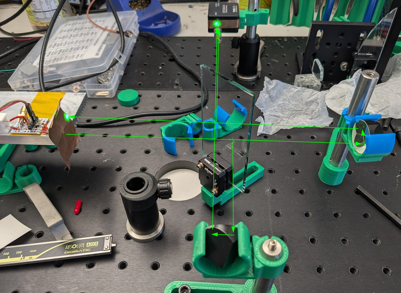
I figured that perhaps the above wild fluctuations were due to either a horrible power supply (almost guaranteed) or strong back reflections from my plain glass beam splitter. I can’t find any good cheap laser drivers online unfortunately so I figured I would change the setup to a Mach zehnder interferometer, as those don’t create back reflections for the laser. It looks like this now:
But unfortunately I can’t get any fringes at all, no matter how I wiggle and woggle things. part of what makes this difficult I think is that it’s a lot harder to adjust the path length in this configuration and hence hard to get fringes, since the coherence length of the laser is presumably very short with this bad power supply.
Retroreflector Michelson interferometer
Following this guide here, I switched back to a michelson interferometer but with retroreflectors at the end instead of plain mirrors, so the return beam is displaced sideways. This seems to work well, and looks like this:
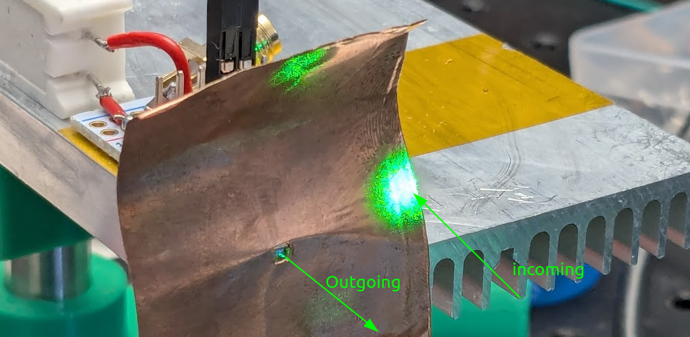
In particular the return beam is no longer shooting back into the laser cavity:
The interference fringes look like this:
When I give one of the retroreflectors a tiiiny tap with my fingers, I get this response:
When the same tap is given with one of the arms obscured, the magnitude of the response is miniscule by comparison.
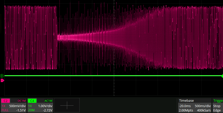
Bandwidth of detector.
In the above graph I have a plain photodiode, a PD15-22C that I’ve stuck in the thorlabs case. When this is put into the scope with a 50R impedance input, the amplitude of the signal is way below the noise floor of the scope, which is sad. So it’s on a 1MOhm impedance, which is for sure killing the bandwidth, as you can see from the above plot - the amplitude of the signal out of the interferometer should be constant, the only thing that is changing is the frequency.
The datasheet says this about the junction capacitance:
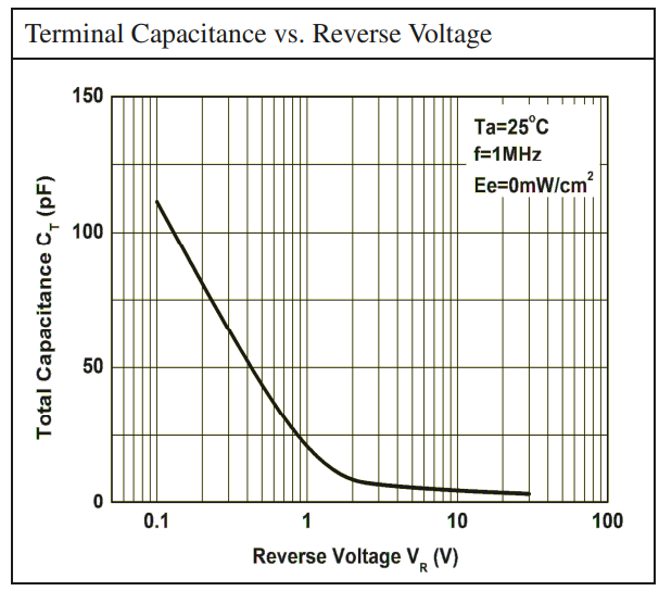
So at my reverse bias of 8V I should be getting about 5pF. At 1Mohm that’s 16kHz. Let’s measure the 3dB point by zooming into the above scope trace to crosscheck that:
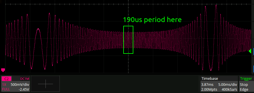
190us == 5.2kHz. That’s ballpark the same I suppose, but would have been nice to be a bit closer to the datasheet. Actually the SMA cable has a capacitance of 30pF/ft apparently, and it’s a 3ft cable, so that would imply a bandwidth of a few hundred Hz, which is clearly way off.
Noise density
This is what the output spectrum looks like:
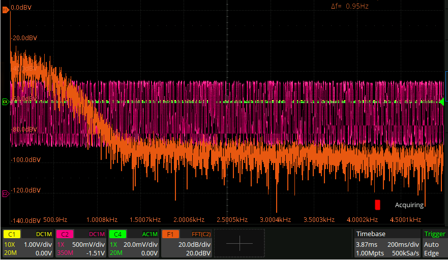
It actually seems to be mostly invariant with how long I make the different arms of the interferometer - what should instead be happening is the output becomes the linewidth of the laser, I think. Since the linewidth is most assuredly not 1kHz here, perhaps there is some other rolloff happening somehow somewhere. Or maybe the laser is modehopping with this spectrum.
Vibration “isolation”:
I propped up the whole breadboard on some folded packing foam, and this is the change in spectrum that resulted:
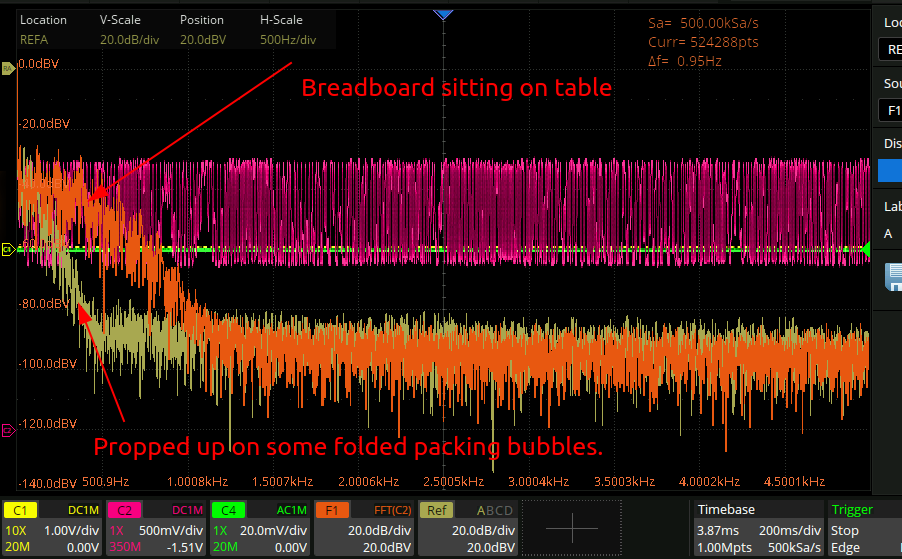
Not too surprising really, but good to see it demonstrated and pretty conclusive. The grumblephone I built previously picked up a huge amount of noise when it was firmly attached to the desk, so that’s a nother